Technical Talk with David Biggs
Words: David Biggs
Bonding with Masonry
By David Biggs
This month’s questions come from mason contractors about architectural design practices. What questions do you have? Send them to info@masonrymagazine.com, attention Technical talk.

Q. A mason contractor writes that they just completed a project. The masonry walls were constructed with a CMU loadbearing wall, an insulated cavity and clay brick veneer. The veneer also had architectural CMU banding. The problem is that after the work was completed, the inspector rejected the work because the movement joints in the CMU wall did not align with those in the veneer. The contractor says the joints were located as approved by the architect. Why is this a problem for the inspector?
A: Thanks for the question! This has come up on other projects. However, it usually doesn’t get discussed. So, let’s look at the options.
- Contractually, you are responsible for placing the movement joints where the architect/engineer locates them. As mentioned in a previous article of Technical Talk (Winter 2018) the masonry standard requires that designers to provide for movement, that includes locating wall movement joints. It is not the contractor’s responsibility to select the joint locations. Therefore as long as your construction matches the design, the inspector has no grounds to reject the work. If the inspector disagrees with the architect/engineer’s selection of joint locations, that should be an issue between them.
- As noted in the previous article, some designers specify that the mason contractor is to select the movement joints locations. We’ve discussed in that article that requiring contractors to select joint locations is not code compliant, but it still happens. Even with this scenario, the architect or engineer must approve joint locations and is responsible for the design. Again, the inspector has no reason to reject the construction provided the constructed joints match the accepted locations.
While both of these are “code-based” responses, let’s consider the theory of masonry movement and the placement of joint locations. It’s common practice for many designers to specify that the movement joints in the CMU back-up as well as those in the veneer align or are placed within a couple feet of each other. But, is that necessary? What could it possibly affect? The likely concern is that the veneer anchors could be pulled in-plane in opposite directions and creates a problem.
First, let’s consider the CMU alone. NCMA TEK 10-2C and 10-3 provide design guidance for movement joint placement and spacing; the code does not give specific recommendations. Typically, CMU movement (control) joints will be spaced between 20 feet and 25 feet on center. These lengths between joints are possible through the use of bond beams and/or horizontal joint reinforcement.
The expected shrinkage of CMU will be due to drying shrinkage, thermal shrinkage and carbonation. See NCMA TEK 10-1A for a detailed discussion of each effect.
Using the drying shrinkage and thermal expansion coefficients in TMS 402, Building Code Requirements for Masonry Structures, we should be able to calculate the maximum anticipated shrinkage for a CMU wall due to those two effects. Carbonation is mentioned in TMS 402, but no specific coefficient is provided; NCMA TEK 10-1A will be used for that.
Let’s make an extreme assumption that a wall will be constructed with movement joints at 24-8” on center while the temperature was 100°F. We’ll also assume wall was not enclosed and thermally-controlled until after the temperature had dropped to 32°F. That’s a 68°F temperature differential.
Looking at the components of shrinkage:
Drying shrinkage = 0.5sl from 2016 TMS 402, Section 4.2.5.1. sl is the total linear drying shrinkage determined from ASTM C426 as noted in TMS 402. The commentary for TMS 402, Section 4.2.5 lists this as 0.065%.
For our wall: Shrinkage = 0.5 (0.00065)(24.67 feet x 12 in/ft) = 0.10 in.
Thermal shrinkage = 0.0000045 (in./in./°F) taken from 2016 TMS 402, Section 4.2.3 x (68°F) x (24.67 feet x 12 in/ft) = 0.10 in.
Carbonation = 0.00025 in./in. from NCMA TEK 10-1A x (24.67 feet x 12 in/ft) = 0.08 in.
Clearly, this is an extreme example. These carbonation and thermal effects would not likely occur simultaneously. Despite that conservatism, the total shrinkage would be only 0.28 in. for the whole panel. Half of this shrinkage might occur at each end with zero movement in the center or there could be total movement at one end. We’ll assume all the movement goes in one direction for the examples that follow.
Now let’s consider the clay brick veneer by itself. Recommendations for movement joints and spacing are provided by Brick Industry Association (BIA) Technical Notes 18 and 18A. Using Technical Note 18A, we expect the maximum spacing of the movement joint (expansion) will not exceed 25 feet.
While we calculated shrinkage for CMU, we’ll determine expansion for the clay brick because a dominant effect is irreversible moisture growth of the brick. Thermal growth compounds the expansion. For thermal calculations, we’ll make another assumption that the veneer is constructed at 0°F and that summer sun causes the veneer to reach 125°F for a differential of 125°F.
Moisture growth = 0.003 in./in. from 2016 TMS 402, Section 4.2.4 x (24.67 feet x 12 in/ft) = 0.89 in.
Thermal expansion = 0.000004 (in./in./°F) taken from 2016 TMS 402, Section 4.2.3 x (125°F) x (24.67 feet x 12 in/ft) = 0.15 in.
For this extreme case, the total expansion is 1.04 in. or 0.52 in. at each end.
Now let’s consider these movements, but with differing locations of movement joints.

As a worst case, the combined movement at the joint would be 0.28 in shrinkage + 0.52 in, expansion or 0.80 in.

As a worst case, the combined movement at the CMU joint would be 0.28 in. shrinkage + 0 in. expansion or 0.28 in.
The combined movement at the veneer joint would be 0.14 in, shrinkage + 0.52 in. expansion or 0.66 in.
What does this mean? It shows that offsetting the movement joints actually reduces the potential strain or total movement on the veneer ties that connect the CMU to the veneer. The worst case is when the joints align. I am not aware of reported cases of veneer anchoring systems (adjustable ties, corrugated anchors or horizontal joint reinforcement) creating in-plane problems when joints align, we would not expect there to be problems if they are offset.
Summary:
Designers (architects/engineers) are responsible by code for locating movement joints and whether they can be offset between the CMU and veneer.
Contractors are responsible for locating the joints per the design, but not for selecting joint locations.
Contrary to conventional belief, offsetting movement joints in the CMU backup from the veneer (by design) might be beneficial to veneer ties.
Page Break
Q. Keeping with the topic of movement joints, we got this question from another contractor. A project we are bidding includes a “zipper” joint in the brick veneer. We have looked through the Brick Industry Association (BIA) Technical Notes and can’t find a reference to this type of joint. Since we’ve never seen or built joints like this, are they code-compliant and if so, what concerns should we be aware of for their construction?
A. This is another interesting question. Let’s start with the issue of code compliance. The design standard (TMS 402, Section 4.1.5) for masonry requires that architects/engineers provide for :
“4.1.5 Other effects
Consideration shall be given to effects of forces and deformations due to prestressing, vibrations, impact, shrinkage, expansion, temperature changes, creep, unequal settlement of supports, and differential movement.” So the standard basically directs designers to accommodate deformations, it does not specifically state how to do so.
To answer this question, we will address only movement joints for veneers. This discussion does not include overall building joints which are intended to separate portions of a building to movement from settlement, earthquakes or other actions.
Design
Traditionally, the technical information on the design and placement of veneer movement joints has come from the BIA for clay masonry and NCMA for CMU veneer. If you look at their information as well as other sources such as masonry institutes, you’ll find the traditional movement joint detail is vertical. However, a zipper-shaped joint has been used by various architects with success. It is the architect’s responsibility to be sure the detail allows the movement required. Then, it is code compliant.
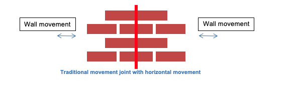
To answer the second part of your question, let’s consider the construction issues associated with “zipper” joints. Any veneer movement joint must allow in-plane horizontal movement as shown below. The red line indicates an open joint with sealant. The key characteristic of these joints is their width. They must be sized for the anticipated horizontal movement. Since most joints are filled with a sealant, the controlling factor for sizing the joint is that it must accommodate movement without over-compressing the sealant or splitting the sealant in tension. Designers should examine the sealants they specify, but many sealants will accommodate 50% movement.

The traditional joint has the added benefit that any incidental vertical movement at the joint might also be accommodated. Sealants do not take this shearing motion well and will likely split.


While the “zipper” allows horizontal movement, it puts the sealant in horizontal shear at the bed joints to do so. Thus, the sealant is more susceptible to failure. The incidental vertical movement capacity of the zipper is limited to about half of the bed joint thickness.
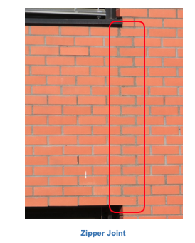
The following photographs show a building at the Czech Technical University in Prague, Architectural Department. I saw the building during construction, but not the veneer. Once the scaffolding was removed, I wondered how they managed to build the veneer with no movement joints. After a few weeks, I finally got a close up look at the veneer to look for cracks. That’s when I found the zipper joints (outlined in the later photograph).


Front Elevation Rear Elevation
The slightly darkened joints are the only indication of the “zipper”. The sealant filled joint was coated in a mortar dust to remove the glossy look of the sealant and to closely match the mortar giving an excellent appearance to the wall. From a distance, the joints are not discernable.

Zipper Joint
Construction
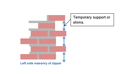
From a constructability perspective, a zipper will take more time and care to install than a traditional vertical joint. The protruding bricks need to be placed without any mortar in the zipper area to provide a clean surface for the sealant. Also, the protruding bricks will have to be temporarily supported by wood blocking or another material until the mortar has set (see left side of zipper).

The right side takes even more skill to keep the zipper clean of mortar because the left side already exists. Again, temporary supports or shims are needed in the bed joints of the zipper to support the newly set bricks.


Once the mortar has set, remove the shims and prepare for sealant. Clean the joint of any residue that could affect the sealant bond. Then add backer rod and sealant. Use colored sealant and broadcast mortar dust as desired to hide the joint.
Design Caution
While the zipper gives another option to designers, they should consider the maintenance of the joint. The sealant life may be reduced due to the zipper configuration. Sealants work best when placed in tension or compression in a vertical joint. The corners of the zipper give added restraint to movement and may cause premature splitting. As previously noted, the shearing action due to horizontal movement could cause splitting as well.
The following photograph is taken from a building completed in 2005. The sealant is now 14 years old. The splitting of the sealant is obvious with all the corners cracked. While some splitting is due to age, much is due to the movement of the zipper.
 Sealant failure at zipper
Removing this sealant, cleaning the joint and replacing with new material will be much more laborious and costly than a traditional vertical joint. This future cost should be considered and discussed with the owner during the design.
Summary:
Zipper joints can be code-compliant when properly detailed and constructed to allow movement.
They do require extra time and effort to construct.
They can be prone to premature sealant failure.
Thank you again for following this column. Remember, by bonding we get stronger! Keep the questions coming. Send them and your comments to info@masonrymagazine.com, attention Technical Talk. If you’ve missed any of the previous articles, you can find them on-line in the archives of Masonry Design (https://MDM.masonrydesignmagazine.com/digital-editions/) starting with the Spring 2018 edition.
David is a PE and SE with Biggs Consulting Engineering, Saratoga Springs, NY, USA (www.biggsconsulting.net). He specializes in masonry design, historic preservation, forensic evaluations, and masonry product development.