MARVELOUS MASONRY- CELEBRATING MASONRY’S HERITAGE: STABILIZING HERITAGE TOWERS
Words: David Biggs, Eugene Legrand
Words: David Biggs and Eugene Legrand
INTRODUCTION
As happens, our marvelous masonry structures are damaged by events such as an earthquake or wind events. More often, time takes its toll due to a lack of funding and maintenance. Without maintenance, serious deterioration can occur and possibly lead to failure. Delayed maintenance might be accentuated when a building changes use and the desire to restore the structure cannot be met with the available funds.
Absent sufficient funding to implement repairs after an event, the only option to save the structure is to provide temporary stabilization.
Many of our heritage buildings, civic halls, religious buildings, monuments, etc. have towers. Stabilizing these magnificent facades can be a challenge. This article addresses some options for stabilization.
There are several approaches to tower stabilization and protection that have been used. Figure 1 shows a brownstone-clad cathedral that was constructed in stages (begun in 1848 and completed in 1902). The lower half of the left tower (arrow) is shrouded in protective netting to prevent shards or chips of brownstone from falling into pedestrian areas. The center entryway is protected with walkway protection to catch any falling debris. The overall façade above those areas was determined to be stable but spalling of the brownstone was a hazard to passersby. So, netting and walkway protection was appropriate but was not used as a true structural stabilization.
The right tower (190 ft tall) was completely stripped, and the brownstone façade was replaced. Façade replacement was required because the older stone (1862 for the right tower and 1888 for the south tower) came from an area of the quarry that lacked the durability of the newer areas. In some locations, 8-inch thick brownstone had deteriorated to approximately 2-inches thick.
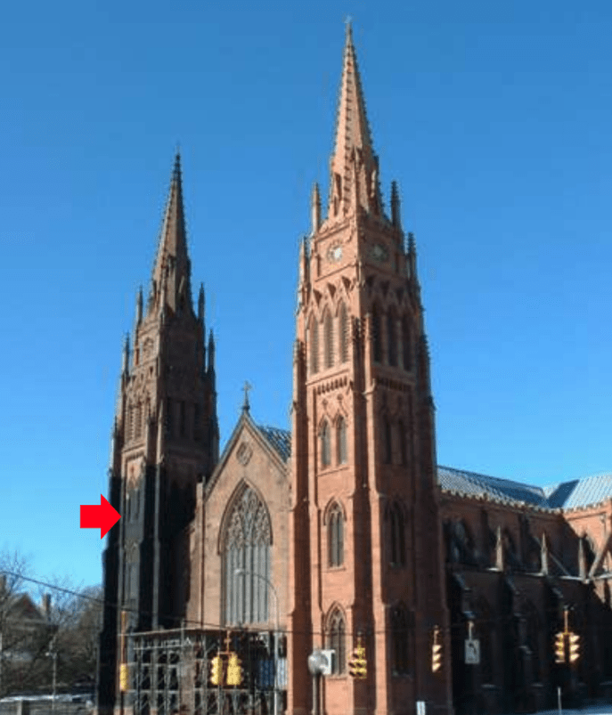 Figure 1 – Netting and temporary walkway protection
Figure 2 shows a church tower from 1889. One of the corner buttresses bowed outward, became unstable, and needed to be rebuilt (see the box in Figure 2). However, to accomplish that feat without removing the tower above required a stabilization concept.
 Figure 2 – Tower Stabilization
 The concept used was to install pins into the stones above the area to be removed and encircle the upper stone of the tower with cables to retain the stone tight at the corners.
Figure 3 shows a graphic of the stone above the desired removal area. To prevent the stone weight from sliding down during lower buttress removal, threaded stainless steel rods were needed to retain the upper stones. Figure 4 shows the actual installation of the stainless steel rods being set in an adhesive.
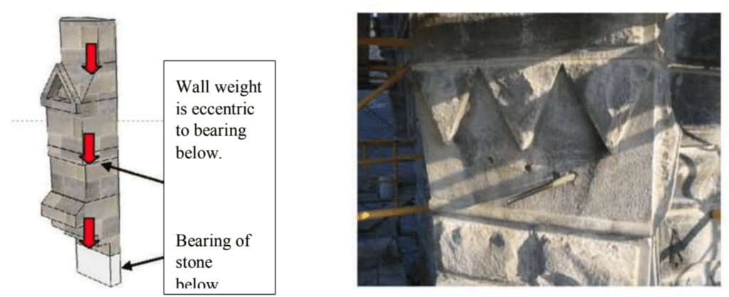 Left: Figure 3 – Graphic of stone loads above removal area Right: Figure 4 – Adhesive anchors
Figure 5 shows the cable concept schematically. The cable only retains the corners. Wooden crush plates are used to prevent stone damage as the cable turns the corners.
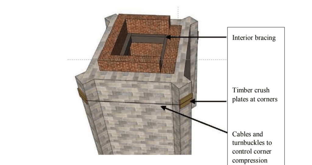 Figure 5 – Cable concept
Figure 6 shows the position of two rows of cables above the proposed removal area. The cables effectively prevent the upper stones from rotating outward due to the eccentricities of the upper stones.
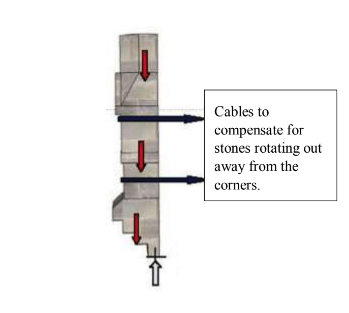 Figure 6 – Cable positioning
Figure 7 shows the lower stone removed. The steel rod locations are visible above. Subsequently, the portion of the damaged buttress was rebuilt and anchored to the existing wall.
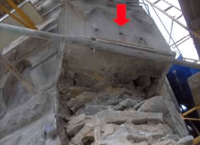 Figure 7 – Removals complete below
The point here is that both the steel rods and the cabling made up the stabilization system. Either one alone would not provide an adequate level of safety to retain the upper stones.
Together these two examples of tower stabilization indicate that the solutions vary based on the conditions of the masonry and the condition of the overall walls or buttresses. Every building has to be individually evaluated.
CASE STUDY
Background
The following project (Figure 8) had its own unique circumstances. Between 1885-1887, it was constructed as a high school and remained a school until 1995. It remained vacant until 2008 and is currently a senior center for the town.
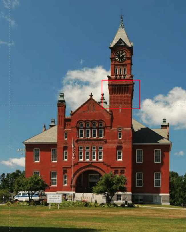 Figure 8 – Winchendon, MA Senior Center (East Elevation)
This Late Victorian/Romanesque masterpiece with a marvelous clock tower was placed on the National Historic Register of Places in 1988. The exterior walls of the building are typically multiple wythes of brick (common brick interior plus face brick). Much of the exterior trim work is brownstone banding and arches.
By 2019, concerns over deterioration and cracking led town leaders to engage a consultant to evaluate the entire building, including the facade. Their January 2020 condition assessment identified $5.3 million of needed repairs. Recommended building repairs were deemed Critical, Additional, or Long-term (https://www.townofwinchendon.com/sites/g/files/vyhlif4051/f/uploads/20200211153658358.pdf).
In December 2020, an area of the clock tower façade collapsed (see box on Figure 8 for location). This area had been deemed Critical in the assessment report and was slated for repair and rebuilding. The assessment report provided photographic documentation of the condition before collapse (Figures 9 and 10). The arrows have been added to the report photograph; red indicates an area of bulging brick, and yellow signifies significant cracks.
This area of the clock tower was ornately detailed with protruding brick headers, corbeling, brownstone arches, and trim.
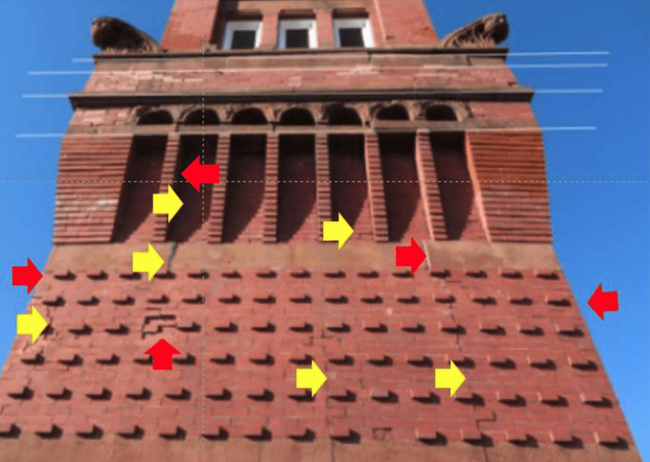 Figure 9 – Clock Tower before façade collapse (East Elevation)
Figure 10 shows some of the critical displacement at the corbeled section of the wall. Since the face brick is headered to the backup wythes, bulging indicates either broken or displaced headers. Either way, the attachment of the face brick has been compromised. There are also signs of displacement of the brownstone banding.
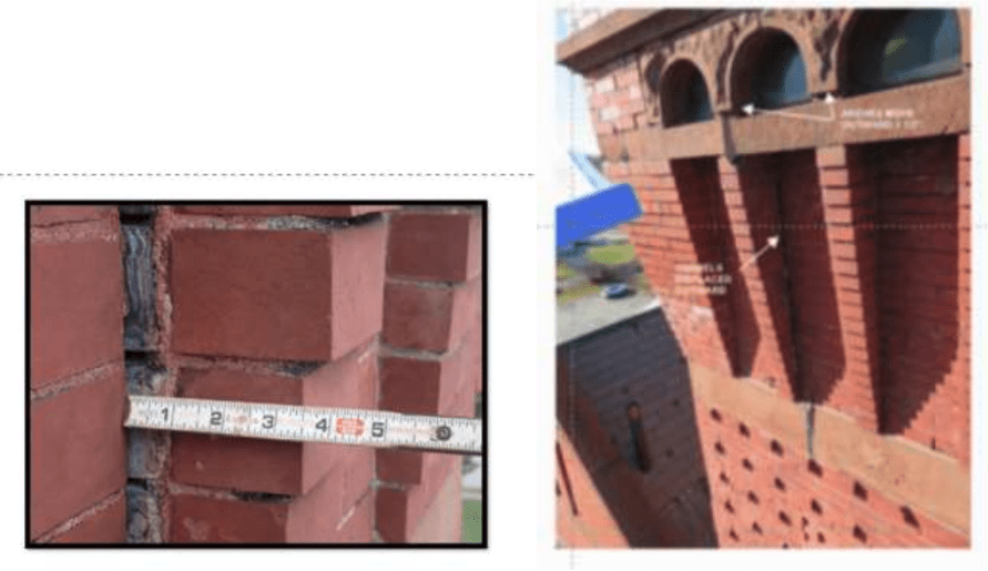 Figure 10 – Corbel displacement (East Elevation)
In addition to the cracking indicated in Figure 9, Figures 11 and 12 show significant corner cracking.
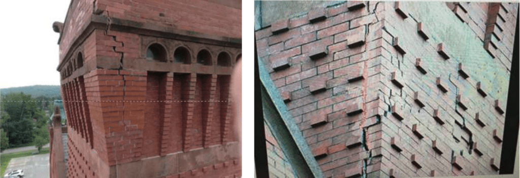 Left: Figure 11 – Northwest corner cracking Right: Figure 12 – Southeast corner cracking
The collapse on the East elevation is shown in Figure 13. The arrows show additional cracking below the failure.
A close-up view of the southeast corner is shown in Figure 14. In this photograph, you see:
- White efflorescence from previously broken brick headers and stretchers. Water infiltration into the cracked wall area caused efflorescence on the broken ends.
- Red units are newly broken headers. These units were likely keeping the bulging façade intact just before the collapse. None of the headers pulled out of the wall.
- There are intact headers where the mortar bond to the adjacent stretcher units failed.
- Above the collapsed area, the corbeling appears to have stabilized the collapse area as the face brick overhangs.
 Figure 13 – Collapse area (East Elevation)
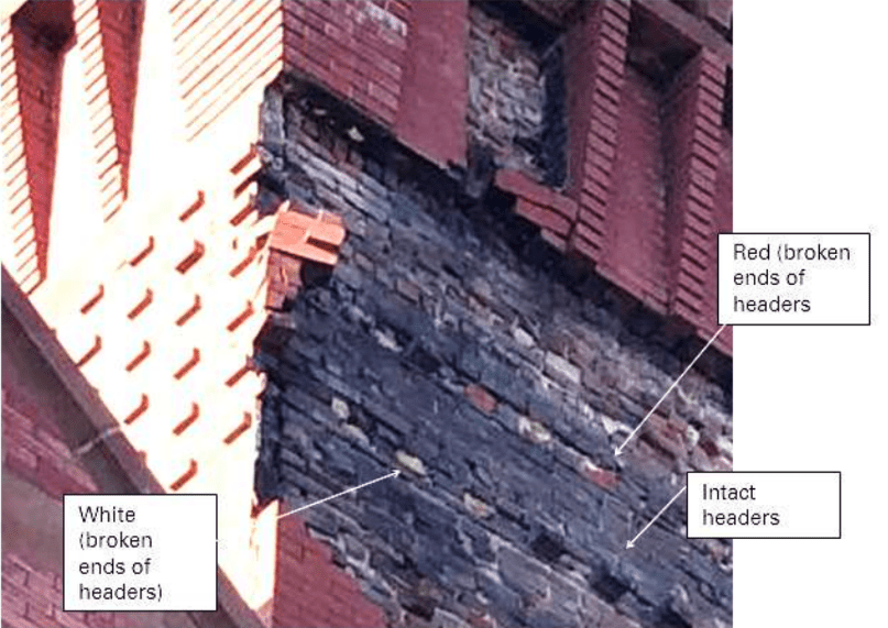 Figure 14 – Close-up of Southeast corner
Challenge
Following the collapse, town officials issued an emergency contract to Legrand Masonry (https://legrandcompanies.com/) to stabilize the clock tower. Legrand’s concerns included:
- Winter conditions in New England. The stabilization needed to be performed in December 2020 and January 2021.
- Working at height. 125-foot lifts would be required to access the collapse area approximately 90 feet above grade.
- The potential collapse of the upper portion of the tower. Safety was a prime concern.
- One major challenge was this occurred during the Covid pandemic. Legrand Masonry teamed with Biggs Consulting Engineering to develop a stabilization plan. The project is in western Massachusetts and Biggs was about two hours from the site in New York State. In normal times, that is not a problem. But during that period of the pandemic, travel between states was not allowed without a 14-day quarantine. It was unreasonable to expect quarantining in both directions for a one-day site visit from New York. So, the site inspection and engineering work had to be done in a hybrid manner with Legrand Masonry being on-site and Biggs Consulting virtual.
With the Condition Assessment report as a background, Legrand Masonry performed additional site observations to provide information to develop the engineering solution. This included an interior inspection of the clock tower and an exterior inspection aided by the local Fire Department with its ladder truck.
The interior at the arches level is shown in Figure 15. In the collapse area, the wall was verified as approximately 21.5 inches thick including the face brick. The face brick was anchored by the headers. The brownstone banding was set in mortar but without any anchors.
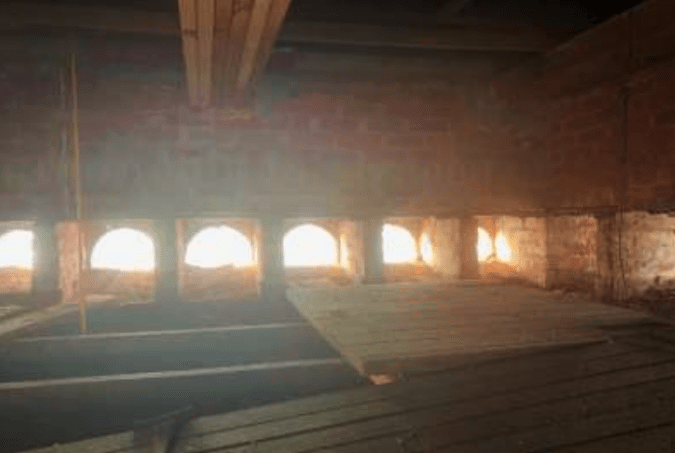 Figure 15 – Interior of Clock Tower
Stabilization Scheme
With worker safety in mind, a two-phase stabilization scheme was developed.
Phase 1 – Stabilize the brickwork above the collapse area so masons could safely work in the collapse area.
Phase 2 – Stabilize the collapse area by shoring the upper masonry and enclosing it in weather protection.
Phase 1 Stabilization
The project team considered conventional stabilization schemes like cabling the upper brickwork and installing retrofit anchors. But, each method had drawbacks. The cabling would be difficult to restrain the entire face of the brickwork; timber bracing would have to supplement the cables. The edge pressure of the cables would be excessive due to the corner damage. Cold-weather installation of adhesive anchors would be a problem. In addition, a large amount of drilling could further destabilize the damaged face brick.
The solution selected was to shrink-wrap the tower. The shrink wrap would be a structural component of the stabilization and not just an enclosure. When most people hear of shrink wrap, they think of Figure 16. It’s a lightweight, weather-tight polyethylene covering for winter storage, usually about 6 or 7 mils thick.
 Figure 16 – Shrink-wrapped boat
However, shrink wrap has many industrial uses, such as for shipping, enclosing scaffolding for dust and debris confinement and/or for privacy, and temporary roofs (Figures 17-19).

Left: Figure 17 – Shipping wrap Right: Figure 18 – Scaffolding enclosure
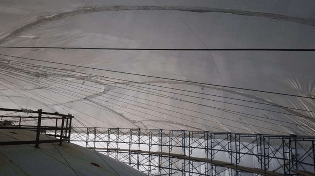 Figure 19 – Temporary roofing
The common plastic polymers are low-density polyethylene (PE) or polyvinyl chloride (PVC). Another form of shrink wrap is made from polyolefin (POF). For the tower stabilization, the shrink wrap material selected was 12-mil premium industrial grade, flame-retardant polyethylene available from Dr. Shrink (www.dr-shrink.com). The material selected shrinks in both directions. Technical advice was provided by Gary Cillis of US Shrink Wrap Inc. (https://usshrinkwrapinc.com/) who supplied and installed the shrink wrap.
How does shrink wrap work?
- During manufacturing, the plastic film is stretched. Once it is wrapped around an object, heat is applied with a heat gun, and the polymer molecules realign to their original position and shrink the film.
- The material selected is available in rolls colored white, blue, or clear; white was selected.
- The material has inhibitors to slow down UV degradation. The manufacturer recommends planning on a 12- to 16-month service life. PE and PVC shrink wrap are recyclable as well.
What are the benefits of using the shrink-wrap on the tower stabilization?
- The wrap can be installed above the collapse area from lifts and create a safe work area below.
- It can be placed in contact with masonry. The entire perimeter of the tower was wrapped.
- When the wrap shrinks, it exerts an inward pressure on the face brick (see the plan of the tower in Figure 20). The loose bricks are then held onto the wall and retained structurally by the wrap.
- The wrap could be installed in cold weather working from lifts.
- The heating process of installing the shrink wrap can be started, stopped, and restarted so the installation can be done incrementally.
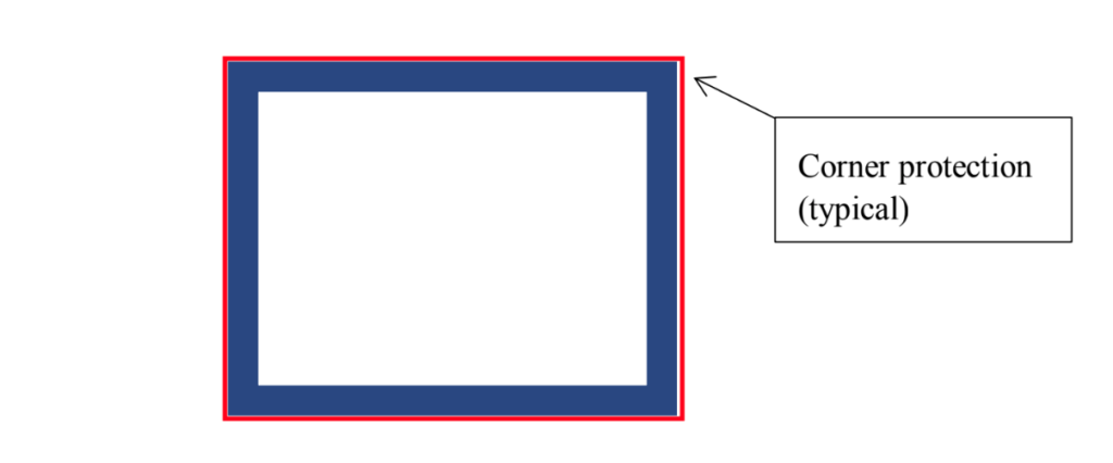 Figure 20 – Shrink wrap system
Using cables would retain the corners (see the plan of the tower in Figure 21 and not cover the entire wall surface. To hold the brick, stiff backs have to be installed to hold the face brick. Then a tarp would be required to catch loose pieces. This would be more time-consuming and costly and not perform as well as the shrink wrap.
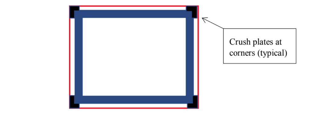 Figure 21 – Cable system
Since the shrink wrap exerts pressure on the walls, loose brick needed to be stabilized before the wrap was installed, so the wrap did not cause the loose brick to shift. This required some crack filling. Figure 22 shows a corner that was stabilized. For winter work without the possibility of temporarily heating the masonry, a Type O mortar mix was selected for the filling. It was pre-hydrated for 1 to 1/1/2 hours before installation. The goal was not to “repoint” the joints where the mortar bond to the brick is important; here, the goal was to fill the joints to avoid brick movement by the wrap. Aesthetics were also not a concern.
Figure 23 shows the wrap installed above the collapse area. The wood framing will be discussed as part of Phase 2 of the stabilization. In the Figure, the wrap at the level of the framing is still incomplete.
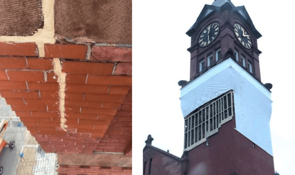 Left: Figure 22 – Mortar filling as stabilization Right: Figure 23 – Phase 1 shrink wrap
Phase 2 – Stabilization
With Phase 1 complete and most of the safety concerns about the upper masonry relieved, efforts turned to installing wood framing as shoring (Figure 23) to further support the upper masonry. Winter conditions and cost prevented infilling/rebuilding the collapsed area with brick.
Figure 24 shows the shoring installed and shimmed tight to the upper brick. The framing transfers the weight of the upper masonry to the area below the collapse as it was originally supported. The lower edge of the shrink wrap is retained by a cable because it shrinks vertically as well as horizontally
The wood shoring was anchored back to the structural brick (Figures 25 and 26). The top and bottom of the shoring were screwed to steel angles that were secured to the masonry with mechanical anchors (no adhesive due to cold weather).
Normally, masonry restoration anchors would be used in the remaining brick below the collapse area. In this case, 2 x wood boards were used to retain the remaining top courses from bowing outward due to the vertical shoring loads.
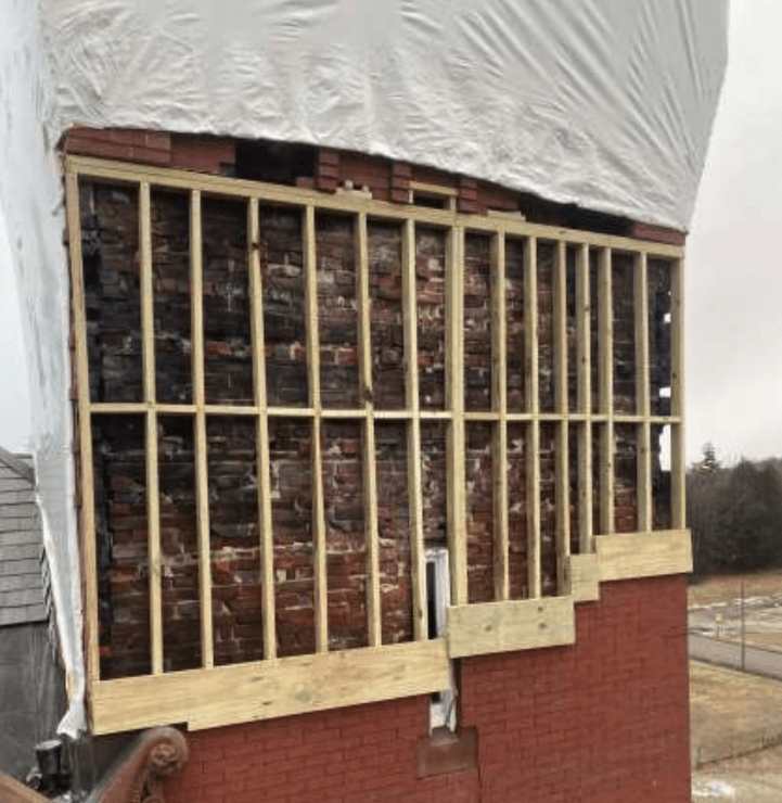 Figure 24 – Phase 2 shoring stabilization
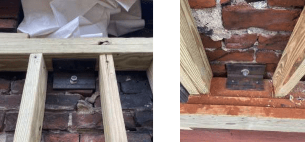 Left: Figure 25 – Top anchorage Right: Figure 26 - Bottom anchorage
Once the framing was complete, the shrink wrap installation was completed (Figure 27). The wrap provides some moisture protection for the framing also. Figure 28 is the condition in Sept. 2021.
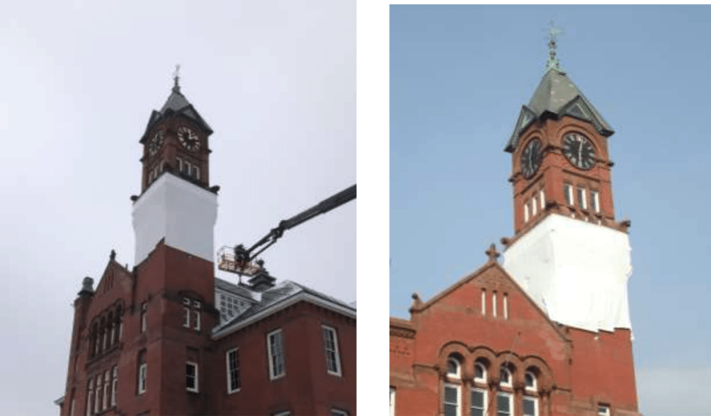 Left: Figure 27 – Northeast corner January 2021 Right: Figure 28- Southeast corner September 2021
Conclusions and Lessons Learned
- Shrink wrap has been used to enclose scaffolding and buildings for decades for containment and privacy. However, for specific cases, it offers new options for providing structural stabilization simultaneously with confinement and privacy.
- The wrap on this project provided structural stabilization to the tower as well as weather protection for the wood shoring.
- All shrink wrap is not the same. Industrial grade material is required for stabilization. PVC shrink wrap is flammable and should not be used.
- Owners must be aware that the wrap material is only for temporary use. Manufacturers suggest a 12- to 16-month service life. The wrap should be re-inspected every 4 to 6 months.
- For this project, visual inspections are required every six months to determine if the material is losing any effectiveness. This adds to the urgency for obtaining funding to implement a permanent fix.
- Some applications may only require wrap material with uni-directional shrinkage ability and others bi-directional. The wrap should be selected accordingly, and engineers should plan for the anchorage. A bi-directional wrap was used for this project.
- No design properties for the wrap are available for structural engineers. Anecdotal information indicates that the confining pressure of the shrink-wrap might approach 450 psf on the surface, but no testing data was found in support of that value.
- Town officials are seeking funds to implement the recommendations of the Conditions Assessment report, which includes a rebuild of the collapse area.
Authors:
David Biggs is a US-based structural consultant from Saratoga Springs, NY, and a regular columnist for MASONRY (Marvelous Masonry series) and Masonry Design (Technical Talk) magazines.
Eugene Legrand is Vice President at Legrand Masonry, Inc., Athol, Massachusetts specializing in masonry construction and restoration.
Acknowledgments:
The Town of Winchendon and Keith Hickey, Town Manager, for providing the Conditions Assessment report and use of the photographs.
Tighe & Bond, Westfield, MA and sub-consultant Structures North, Salem MA for the Winchendon Senior Center, Conditions Assessment, January 2020 and the photographs from that report.
Stabilization construction photographs by Legrand Masonry, Inc.